How Does the L2 Bracelet Work?
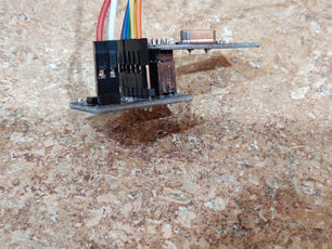
The L2 bracelet is based off of a RX/TX nRF24 radio transmitter and receiver. The bracelets come in a two pack. One of them, which is attached to the transmitter, is worn by the child with special needs. The other one is attached to the receiver, and worn by the caregiver. The two bracelets send radio waves to each other. Once the bracelets lose connection, because the child moved about 15 feet from the caregiver, the caregiver's bracelet will blink and beep, notifying him/her that the child started to move away. We tested the physical prototype and it loses link and 15 feet!
WATCH OUR WORKING PROTOTYPE!
L2 Bracelet Video
Your One Stop Shop for Emotion and Information
The recorded narration was done by:
Hindy Feigenbaum- Project Lead/Manager

The Coding
Receiver Code
L2 Bracelet
//add the following libraries
#include <SPI.h>
#include <nRF24L01.h>
#include <RF24.h>
const uint64_t pipe = 0xE8E8F0F0E1LL; //name the radio-wave system
RF24 radio(9, 10);
int rocket[2];
void setup()
{
radio.begin(); //Turn on the radio-waves
radio.openReadingPipe(1, pipe);
//Allow the Rx/Tx to talk to each other
radio.startListening();
//Start accepting the information from the Tx
Serial.begin(9600);
//Turn on serial monitor
pinMode (3, OUTPUT); //pin 3 is the light
pinMode (8,OUTPUT); //pin 8 is the buzzer
}
void loop()
{
if (radio.available())
//if you are able to pick up the Tx signal
{
radio.read(rocket, sizeof(rocket));
//Then read the array as regular and give no response
Serial.print(rocket[0]);
Serial.println(rocket[1]);
digitalWrite (3,LOW); //Light is off
noTone (8); //Buzzer is off
}
else //if the signal is not available
{
Serial.println("No Radio");
delay (50);
//Write "No Radio" to serial monitor
//Blink the light
digitalWrite (13,HIGH);
delay (100);
digitalWrite (13,LOW);
delay (100);
//Buzz the Buzzer
tone (8, 1000, 200);
}
delay(10);
}
Transmitter Code
L2 Bracelet
//Include the following libraries
#include <SPI.h>
#include <nRF24L01.h>
#include <RF24.h>
//name the radio- wave systems
const uint64_t pipe = 0xE8E8F0F0E1LL;
RF24 radio(9, 10);
int elephant[2];
void setup()
{
radio.begin(); //Turn on the radio
radio.openWritingPipe(pipe); //Turn on the ability for the Tx/Rx to talk to each other
}
void loop()
{
//make the value of array elephant equal to the value of analogRead
elephant[0] = analogRead(A0);
//make array elephant equal to 7
elephant[1] = 7;
//Tell the Rx the size of the array
radio.write(elephant, sizeof(elephant));
}
Flow Chart/Operations


TinkerCad
The Best of our Project- Simulated!
TinkerCad does not offer any way to stimulate two, unattached Arduino boards. Therefore, we used TinkerCad to stimulate the cause and effect, but the boards are connected. They also do not offer an nRF24 stimulation, for the same reason, so we used a potentiometer instead. Our goal is to show how if the potentiometer, which is on the Arduino that is representing the transmitter (the child), reads too high (representing the child that has wandered too far), then the buzzer will sound and the light will blink, on the Arduino representing the receiver (caregiver).
Watch the simulation below!
Simulation
Play around and enjoy!
Move the potentiometer and see what happens to the buzzer and light!

Bill of Materials/Costs
Due to COVID-19 we were unable to use most of our materials, because they need to be soldered together. Here is the list of materials that we had the ability to use.

COVID-19 Bill of Materials/Costs
Click on the item to be taken to its link
All items were ordered from Amazon
1. 2 Arduino Boards- Provided by CIJE/ School
2. LED- Provided by CIJE/ School
3. Piezo Speaker- CIJE/ Provided by School
4. Breadboard- Provided by CIJE/ School
5. Wires- Provided by CIJE/ School
6. Rx/Tx Transceiver (nRF24) -$11.99
Total Costs: $11.99
Unfortunately, we were unable to bring our prototype to the next level and make it more realistic due to COVID-19
Pre COVID-19 Bill of Materials/Costs
Click on the item to its link
All items were ordered from Amazon
1. 2 mini Arduino Boards- $23.98 (each one was $11.99)
2. Battery Holder- (10 Pack)- $10.98
3. Mini LEDs (25 Pack)- $9.99
4. Batteries (10 Pack)- $5.99
5. Rx/Tx Transceiver (nRF24)- $11.99
6. Piezo Speaker- Provided by CIJE/ School
7. Breadboard- Provided by CIJE/School
8. Wires- Provided by CIJE/ School
Total Costs: $62.93

We put pictures of both the COVID prototype and the products that we bought before Coronavirus throughout the website.


